
 English
 русский
 Français
 Español
 Indonesia
 Deutsch
 عربى
عربى 中文简体
中文简体
Overheat & Overpressure Protection in Sterilizer Design
Posted by Admin | 23 Apr
Content
- 1 Why Overheat and Overpressure Protection Systems Matter in Every Sterilizer Design
- 2 Core Risks: What Happens Without Proper Protection
- 3 Design Fundamentals: Layered Protection Architecture
- 4 Key Setpoints and Interlocks That Prevent Incidents
- 5 Practical Implementation: Sensors, Valves, and Logic You’ll Need
- 6 Validation, Compliance, and Maintenance
- 7 Design Trade-offs and Smart Choices
- 8 Takeaways: Make Protection Part of the Performance Strategy
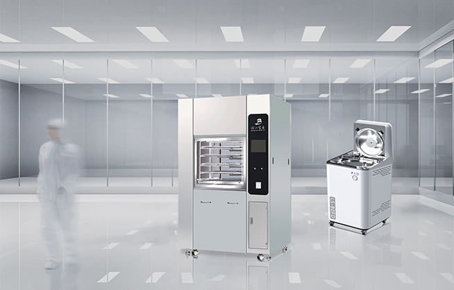
Why Overheat and Overpressure Protection Systems Matter in Every Sterilizer Design
Sterilizers operate at the edge of thermal and mechanical limits to ensure microbial kill, which makes overheat and overpressure controls more than “nice-to-haves”—they are core safety and performance features. When temperature or pressure creeps beyond set points, you risk chamber rupture, scalding steam release, product damage, cycle failure, and regulatory violations. Here’s a practical, engineering-focused look at what to implement and why it changes outcomes.
Core Risks: What Happens Without Proper Protection
Thermal Runaway and Material Degradation
Uncontrolled heating leads to thermal runaway—heaters keep delivering energy faster than the system can dissipate it. This can char bioload indicators, warp trays or packaging, and compromise instrument longevity. In ethylene oxide (EtO) and hydrogen peroxide plasma systems, excess temperature accelerates reagent decomposition and can create explosive byproducts.
Pressure Excursions and Structural Failure
Overpressure strains the vessel beyond its design code (ASME Section VIII for pressure vessels). Seals blow out, door gaskets extrude, and sight glass can fail. Even sub-catastrophic events create leak paths and loss of sterility assurance, while major failures risk personnel injury from steam or gas release.
- Cycle invalidation: Exceeding validated limits voids the sterilization claim.
- Hidden damage: Microcracks in welds or fatigue in door latches reduce lifetime.
- Operational downtime: Unplanned maintenance and requalification delays.
Design Fundamentals: Layered Protection Architecture
Sensing Redundancy and Placement
Use at least two temperature sensors (PT100/RTD or thermocouples) and two pressure transducers to avoid single-point failure. Place one set near the load zone and another near the steam inlet or reagent port to capture gradients. Incorporate a mechanical gauge for maintenance verification.
- Independent signal paths and ADCs to prevent common-mode errors.
- Periodic cross-check: PLC compares sensors; if divergence exceeds tolerance, trigger safe state.
Control Logic: Normal vs. Safety Channels
Separate routine PID control from safety interlocks. Normal control adjusts heaters and valves for setpoints; safety channels override immediately when limits are breached. Implement hard-wired relays for heaters and solenoid valves that trip on loss of power or over-limit signals.
Mechanical Safeguards: Relief and Containment
Install a spring-loaded pressure relief valve sized for worst-case steam or gas generation, with discharge routed to a condensate receiver or scrubber. Include a burst disc as a fail-safe secondary device. Door interlocks should prevent opening above safe pressure and temperature.
Key Setpoints and Interlocks That Prevent Incidents
Typical Thresholds (Adjust per Validation)
| Parameter | Normal Control Range | Warning (Soft Limit) | Trip (Hard Limit) |
| Chamber Temperature (Steam) | 121–134°C | +2°C over setpoint | +5°C over setpoint → heater cut |
| Chamber Pressure (Steam) | 2–3 bar(g) | 3.2 bar(g) | 3.5 bar(g) → vent + heater cut |
| EtO Temperature | 45–60°C | +1.5°C | +3°C → gas isolation + purge |
| Hydrogen Peroxide Plasma Pressure | 40–80 Pa | 100 Pa | 150 Pa → plasma off + vent |
Soft limits issue alarms and attempt automatic recovery; hard limits force immediate safe-state actions (heater off, valve close/open, purge sequences) and lock the cycle until a reset procedure completes.
Practical Implementation: Sensors, Valves, and Logic You’ll Need
Temperature and Pressure Sensing
- RTDs (PT100, Class A) for high accuracy; thermocouples where response speed and higher ranges are needed.
- Pressure transducers with overrange protection; select sanitary diaphragm types for steam.
- Regular calibration with traceability to national standards; include drift detection in firmware.
Actuation and Relief
- Fail-safe solenoid valves (normally closed) for steam/gas inlets; vent valves sized for rapid depressurization.
- Heater contactors with safety relays; include thermal cutoffs directly on heater blocks.
- ASME-rated relief valve plus burst disc, discharge piped to safe location with condensate traps.
Control System Practices
- Dual-channel safety PLC or separate hardware interlock board independent of main controller.
- Watchdog timers and brownout detection to default to safe state on power anomalies.
- Event logging with timestamped alarms; require supervisor override for restart after hard trips.
Validation, Compliance, and Maintenance
Standards to Anchor Design
Anchor protection requirements to applicable standards: ASME pressure vessel codes, ISO 17665 for moist heat sterilization, ISO 11135 for EtO, and EN 61010 for laboratory equipment safety. These define acceptable ranges, test methods, and documentation expectations that reduce audit risk.
Routine Testing and Proof
Include factory acceptance tests (FAT) and site acceptance tests (SAT) with simulated over-limit scenarios. Verify relief valve cracking pressure, interlock response times, and alarm visibility. Maintain calibration schedules and replace relief devices per manufacturer cycles.
Preventive Maintenance Playbook
- Monthly: sensor cross-checks, gasket inspection, drain/vent function tests.
- Quarterly: relief valve bench test, PLC safety channel verification, alarm stack review.
- Annually: full validation run at edge setpoints with documented outcomes.
Design Trade-offs and Smart Choices
Balancing Sensitivity and Nuisance Trips
Aggressive limits reduce risk but can cause nuisance shutdowns. Use rate-of-change (dT/dt, dP/dt) thresholds to catch genuine runaway while allowing minor oscillations. Apply hysteresis in alarms to avoid “flapping.”
Cost vs. Reliability
Redundant sensors and hardware interlocks raise BOM costs but cut lifetime service expenses and downtime. For small tabletop sterilizers, prioritize at least one independent thermal cutoff and a certified relief valve; for large hospital or industrial units, add dual-channel PLCs and comprehensive purge/vent manifolds.
Takeaways: Make Protection Part of the Performance Strategy
Overheat and overpressure protection systems aren’t just safety nets; they stabilize cycles, preserve equipment, and defend sterility assurance. By combining redundant sensing, hardwired interlocks, correctly sized relief paths, and rigorous validation, every sterilizer—steam, EtO, or plasma—can run closer to optimal setpoints without courting failure. Design protection into the architecture from day one, document it clearly, and verify it routinely to keep users, assets, and outcomes safe.


